Demos
Here are some of the things that Curan can do for you!
Communicate with the LBR Med in Realtime
To communicate with the robot in real time, two main options exist:
- Start a TCP connection inside the robot controller that broadcasts the current pose in OpenIGTLink format
- Connect yourself through FRI to control the robot at 1KHz
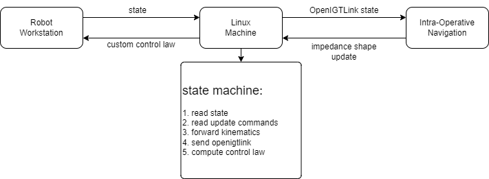
We have implemented both, but to give us the freedom to control the robot whilst doing data collection we prefer the later option. To this end we always have a linux machine running the process FRIPlusBridge which does two things. Establishes a server which broadcast the current pose of the end-effector and a server that broadcasts the joint configuration of the robot in realtime. This is usefull for rendering purpouses. To launch this process go to your command line and run
>> FRIPlusBridge Base 40
where Base if the name of the frame of reference of the world frame, as convention we always use Base in our XML configuration files for Plus. The integer represents the delay between each image which is broadcasted to the outside world. Make sure this delay is large enough to give time to the Plus Server to process the previous combination of Image+RobotPose before sending a new pose.
Calibrate the Ultrasound
warning: To run this application you should start the FRIPlusBridge described in the previous section
Calibration algorithms are an important part of any system, which can either make or break the system. We developed our own calibration algorithm that takes the pose of the flange of the robot and with any phantom, with any geometry**, can provide with the unknown transformation between the flange of the robot and the coordinate system of the ultrasound image.
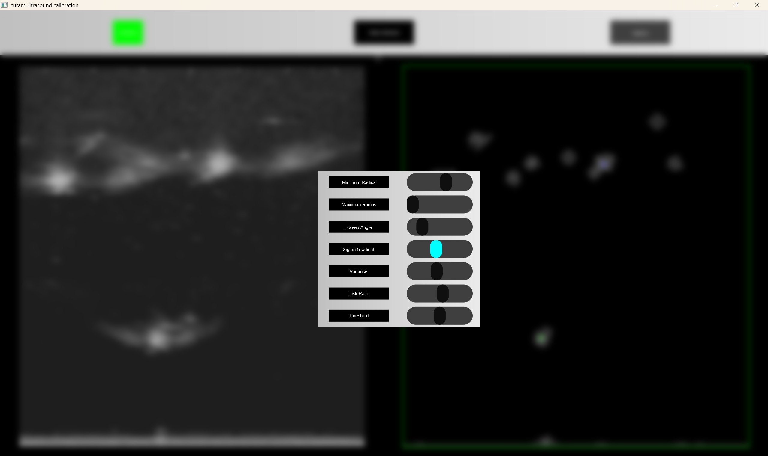
We use our custom UI to render things on screen. This UI has been improved and worked on to simplify as much as possible to the parameterization of the parameters required to calibrate the filter parameters. Lets take a look at how the UI works
Once the program is launched, a window is created where by default the connection with Plus is not established. Launch the PlusServer to collect both pose and images from the robotic system
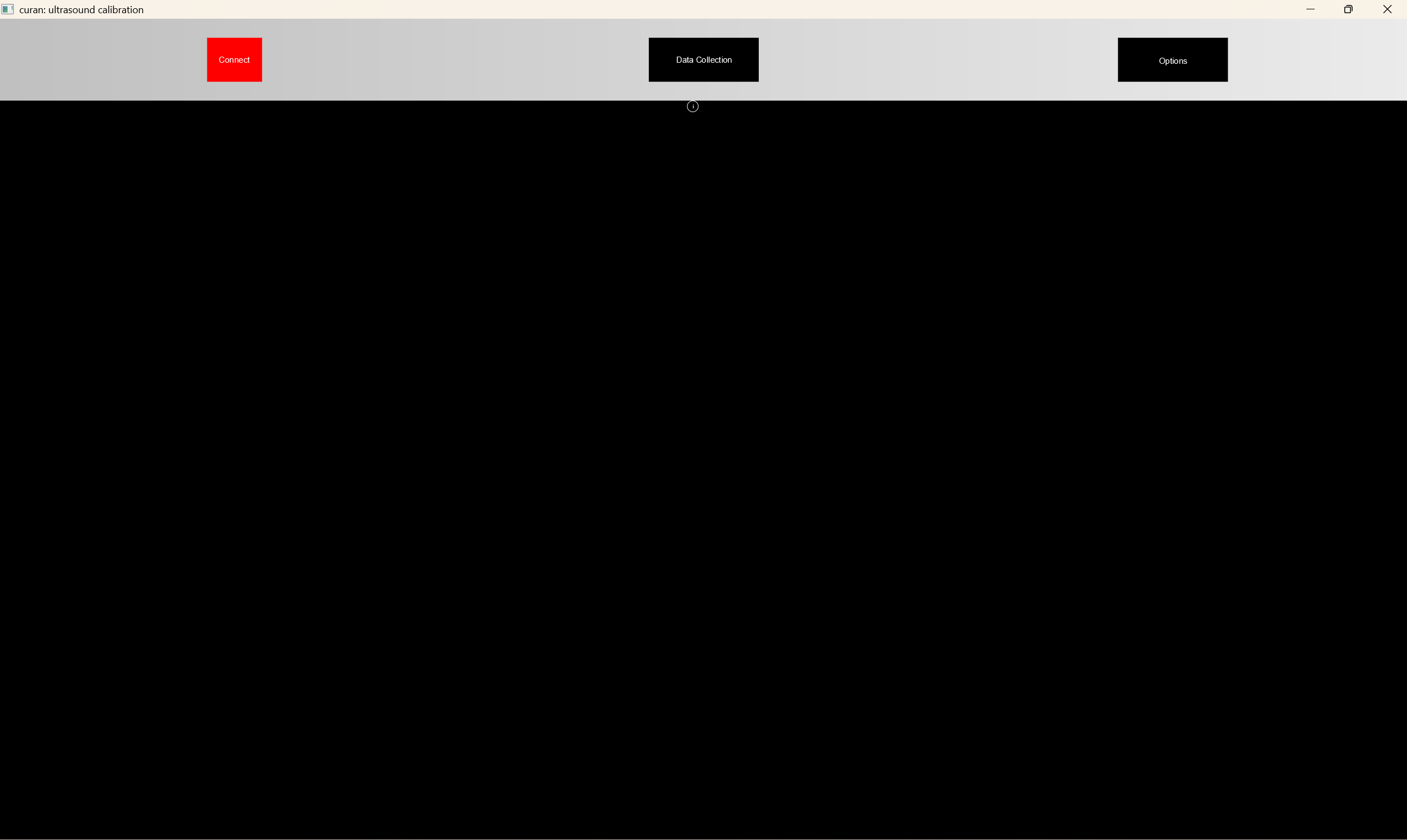
once you have launched PlusServer you can click the connect button. If everything works smoothly, the button will turn green, indicating that the connection to Plus was succefull
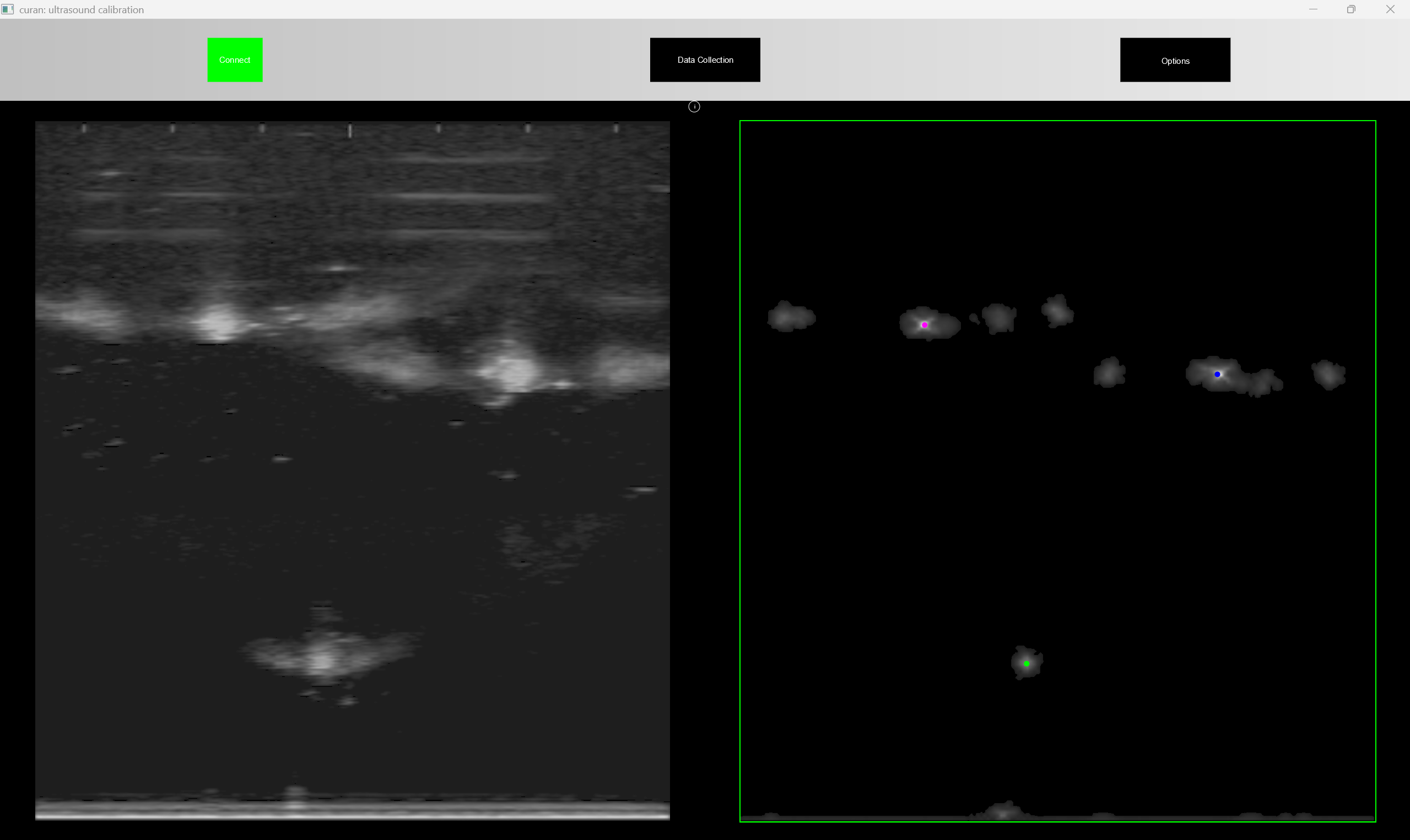
now, the application is receiving an ultrasound image, and we need to filter the positions of the wires in real time from said image. To do this, a series of filters are used, which can be calibrated in real time, so that you can validade if they are working properly or not. Notice that the UI is overlayed over the real image, thus you can verify the quality of the segmentation in real time
to check where the application is identifying wires you can request it to show the wire positions in real time.
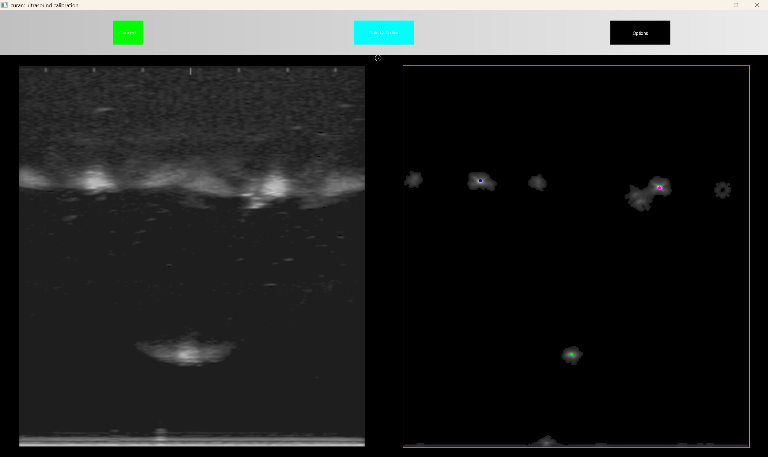
by default if you want to segment N wires, the application will initialy only segment N wires, but as soon as you start the data collection, i.e. put the positions of the wires in a containers a move the robot, the application segmentes N+3 wires, and computes the distance from the previous wires (which is assumed to be correct) and selects which wire of the current frame belongs to the previous segmented wires. This provides robustness to the segmentation in real time. Once you decide you have collected enough data you can terminate the application, i.e. close the window, and a json file will be produced in the current directory of the shell where the application is running. This file looks something like
{
   "homogeneous_transformation":"   0.753799,   0.656902, -0.0163297,  -0.318765 \n   0.566919,  -0.637577,    0.52163,  -0.136224 \n   0.332248,  -0.402462,  -0.853015,   0.125395 \n          0,          0,          0,          1 \n",
   "optimization_error":0.008909722128714685,
   "timestamp":"2023-09-12 14:24:55"
}
where a timestamp is associated with the homogeneous transformation estimated, the optimization error, so that processes further down the stream can decide if the error is small enough and a string, containing the estimated homogeneous transformation.
Visualize the calibrated ultrasound image with the robot display
warning: To run this application you should start the FRIPlusBridge previously described
warning: To run this application you should have previously run the executable that calibrates the setup
You have just performed the calibration of your setup and you want to test if everything is perfect, according to your specifications. We wrote an application where you can see the rendered robot, next to the ultrasound image positioned with respect to the flange of the robotic system
this gives you an idea if the relative position of the system is proper.
Select a region of interest with the flange of the robot
warning: To run this application you should start the FRIPlusBridge previously described
warning: To run this application you should have previously ran the executable that calibrates the setup
Although a trivial task, we wrote a software solution that shows you the pose of the robot in real time as you specify the region of interest in space you wish to reconstruct. Two main reasons for this, first because its fun, second because it gives you some idea of how large this box is with respect to the size of the world.
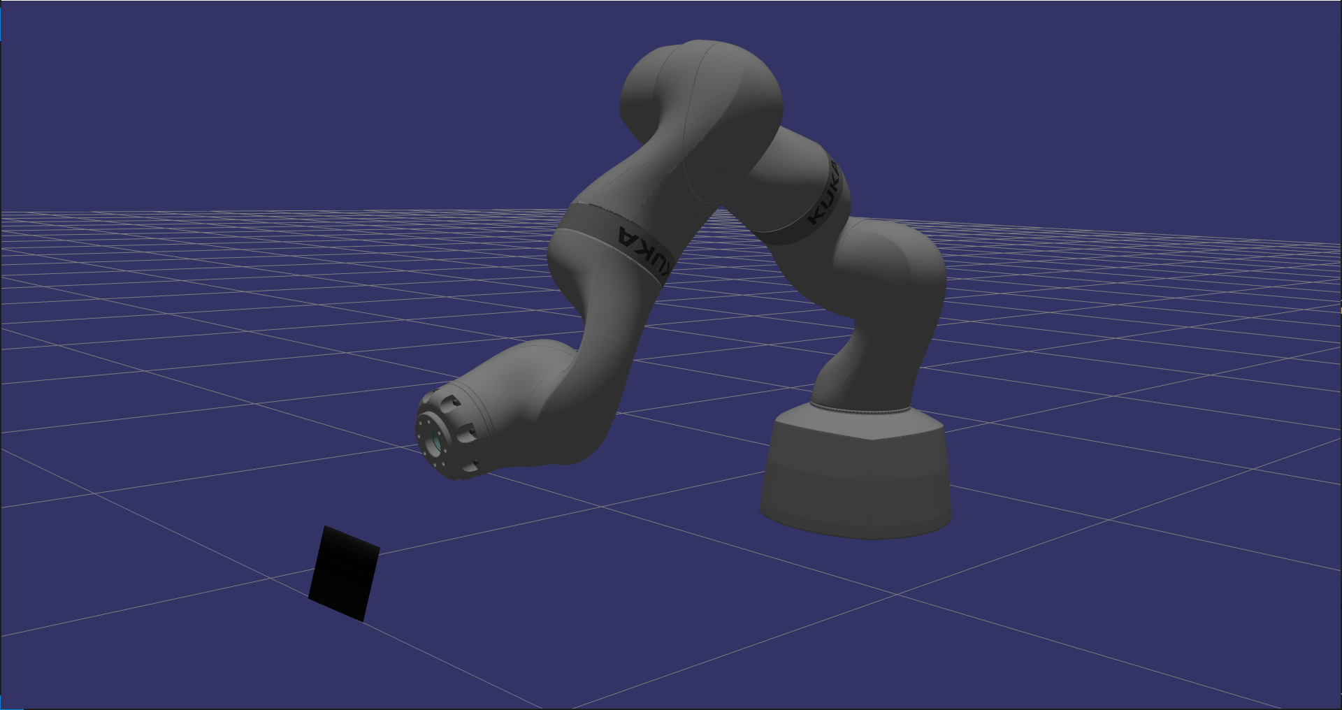
Once you launch the executable the application starts with a default box as shown in the following Figure
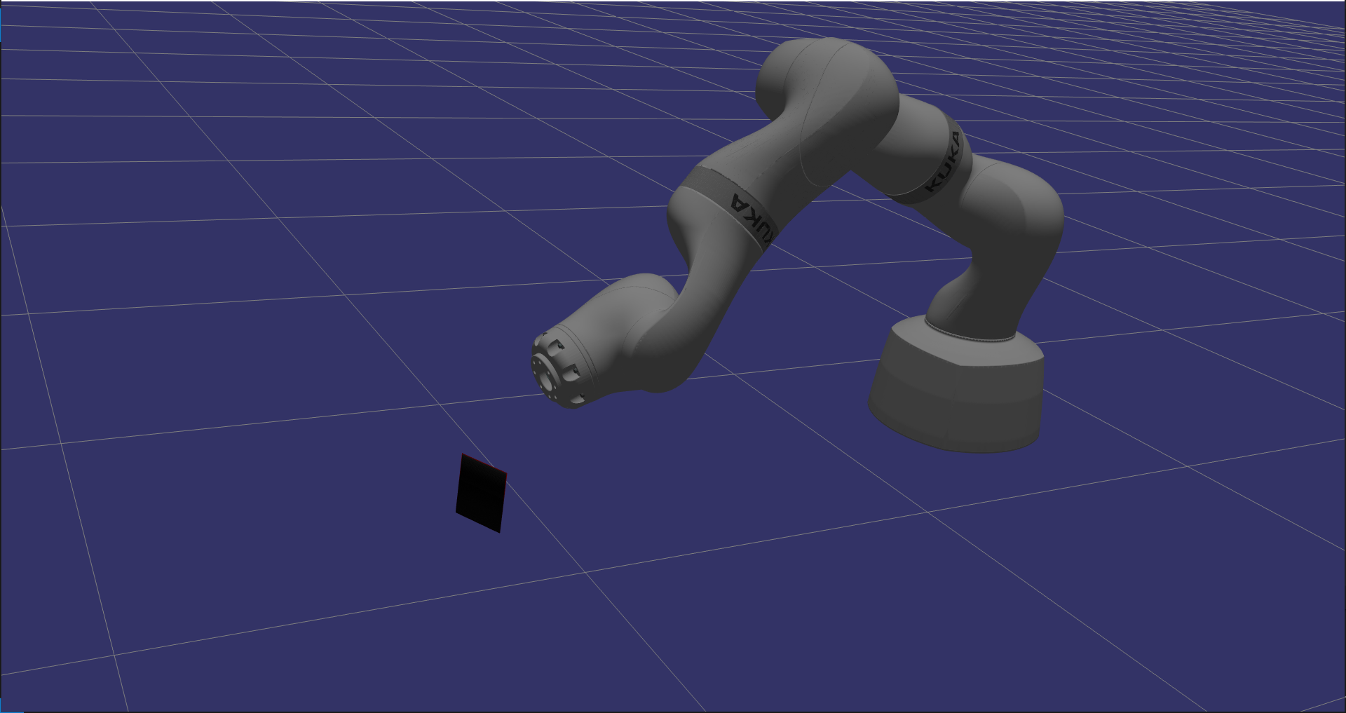
once you signal the program, through the command line, that you want to start collecting poses of the ultrasound image which defines your region of interest you will see this box collapse around the ultrasound image in its current configuration
as you impose motion on the robotic system the code computes the convex hull of all the points previously recorded in the ultrasound images and then, with a smaller subset of points, computes the minimum bounding box which contains these points
this guarantees two things, you are using the all your memory in this region of interest to record the phenomena that is of interest, and the algorithm can keep up in real time with your motion.
Once the program terminates it generates a json file. As an example consider the following file
{
   "direction":"   -0.239035,   -0.906498,    0.348028 \n  -0.0884146,    -0.33661,   -0.937484 \n    0.966977,   -0.254862, 0.000313826 ",
   "origin":"-0.571803 , 0.043331 , -0.179712",
   "size":"0.10739 , 0.0526651 , 0.0844868",
   "spacing":"0.000197 , 0.000197 , 0.000197",
   "timestamp":"2023-09-13 18:45:14"
}
where the direction contains the rotation matrix associated with the bottom corner of the volume with respect to the base of the robotic system. The origin represents the cartesian coordinates of the bounding box in the base of the robot, the size represents the real dimensions of the bounding box and the spacing is deduced by assuming a maximum size in memory that the bounding box can ocupy. From this maximum size in bytes, we divide the size of the box such that an equal resolution is used for all three sides of the bounding box.
This maximum size is important because Vulkan has real limitations in terms of the maximum size of the volume it can render, behond which the volumetric rendering starts flickering.
Do volumetric reconstruction in real-time with high fidelity and low latency
warning: To run this application you should start the FRIPlusBridge previously described
warning: To run this application you should have previously ran the executable that calibrates the setup
warning: To run this application you should have run the executable which defines the bounding box
Humans, similarly to control systems, trive with low latency solutions. We found that previous volumetric reconstruction+rendering techniques were unsatisfactory to our needs. Thus we wrote our own volumetric reconstructor, which is thightly integrated with Vulkan to improve latency of the display and the events in the real world.
Once you start the executable, the application starts rendering the volume in the bounding box you have previously specified. By default, if the current ultrasound image lies outside the bounding box, these pixels are discarded. Only pixels contained inside the bounding box are considerered. To obtain smooth volumes slow motions should be imposed on the transducer.
Consider the following data collection where a relatively high velocity was imposed on the end effector of the transducer.
as you can see, there are larger gaps inbetween the images. Although there are volumetric algorithms which fill these empty voxels, we prefer to only add the information as obtained from our peripherals.
If a slower data collection is imposed then the quality of the reconstruction improves considerably.
With our solution, we are able to render this volume with 5 milliseconds of delay between obtaining an image and injecting it into the desired bounding box and rendering it on screen.
Once the application is terminated, i.e. the window is closed,
Registration of Volumes
warning: To run this application you should start the FRIPlusBridge previously described
warning: To run this application you should have previously ran the executable that calibrates the setup
warning: To run this application you should have run the executable which defines the bounding box
warning: To run this application you should have run the executable that performs volumetric reconstruction
Now that you have voxelized the features of the environment you desired, you can perform registration.
Control the robot with Learning from Demonstration frameworks
Encoding information to a robotic system is a cumborsome task which is both time consuming and error prone. In Curan we provide two solutions we have studied to control the robot in realtime
Task-Parameterized Learning from Demonstration
Limit Cycle Learning from Demonstration
Close to Hard-Realtime Control
RealTime systems are complex beasts, with intricate scheduling problems, thus they are usually very expensive pieces of software. We provide our solution which tries to come close to a realtime system, which meets our specifications.
We don’t claim this piece of software to be realtime capable, we only attest to the results we have been able to achieve so far.
To achieve this almost realtime capability we need to run 3 processes concurrently. The first process communicates with